By Ron Marshall, for the Compressed Air Challenge (CAC)
During the heat of summer, a common complaint in many plants involves the issue of wet compressed air. An ugly slurry of rusty, oily, moisture-laden air—smelling much like an old unwashed gym sock—can collect inside piping and spray out on the precious product of your efforts. When it does, it soils clean surfaces, ruining machinery and contaminating all it encounters. Try as you might, after tuning and maintaining your air-drying units to perfection, the bubbling mass somehow still manages to get past filters, dryers and drains.
In response to the problem, extra filters may be installed, with timer drains blasting hundreds of cubic feet of compressed air in an attempt to cleanse and flush the contamination away. That course of action only makes things worse—and pressure problems start to appear due to the extra load.
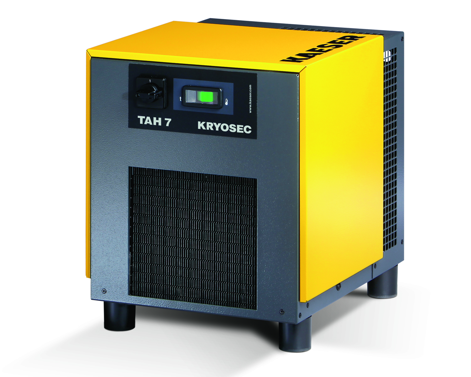
If the above scenario sounds familiar, you may need to pay attention to the following “three 100s” characteristics of your air dryers: Most air dryers sold in North America are rated for compressed air at 100 psi, an inlet-air temperature of 100 F and ambient conditions of 100 F. Read on. . .
Pressure. . .
If your compressed-air pressure is lower than 100 psi, it means higher-than-rated air velocities are flowing inside the piping of the air dryer. Such velocities make it harder to cool the compressed air to the temperatures required to make rated dewpoint—and harder to separate the moisture that’s left when the water vapor condenses.
Inlet temperature. . .
The compressed air produced by your equipment is always completely saturated with water vapor as it enters the air dryer. The hotter the air, the more water vapor it contains. A rule of thumb is that every increase of 20 degrees F in air temperature doubles the amount of water in the air. Dryers can only remove the amount of water they’re designed to handle. The refrigeration circuits of refrigerated dryers (and desiccant beds of desiccant dryers) have been sized only for the amount of water contained in air at the rated 100 F temperature.
Ambient temperatures. . .
The refrigeration circuits in refrigerated dryers need to expel the heat created when the water vapor condenses. The heat-exchanger circuits are designed for 100 F ambient conditions. Hotter temperatures reduce the effectiveness of the dryers.
So, if your facility is experiencing wet-air problems, you would be wise to check on your equipment’s “three 100s.” If they’re out of line, the cause of the wet air should be investigated. For example, ventilation problems can lead to overheated compressor rooms, causing ambient temperatures to exceed dryer ratings. High ambient conditions also affect the air compressors, allowing discharge temperatures to greatly exceed design conditions. This means what might have been diagnosed as a dryer problem is really a ventilation problem.
Note: Even when ventilation is improved, dryers sometimes will still need to be oversized to account for conditions that exceed ratings. CAC’s Best Practices Manual shows correction factors to use in doing this the right way. Information on purchasing the manual can be found at the CAC Website. While you’re there, check out and register for our November Webinar. MT
The Compressed Air Challenge® is a partner of the U.S. Department of Energy’s Industrial Technology programs. To learn more about its many offerings, log on to www.compressedairchallenge.org, or email: info@compressedairchallenge.org.
Continue Reading →

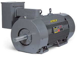 Baldor Electric Co. has introduced a new line of energy-efficient, large AC - GPM Induction Motors. Used in high-torque industrial applications, including pumps, fans, conveyors and compressors, the product line is available in stock ratings 250 – 1000 HP, 2300/4000 Volt, totally enclosed (TEFC), fan-cooled, foot mounted designs.