Archive | Motors & Drives

1555

3:29 pm
May 1, 2015
Print Friendly

Safe Starting of Motors: Check for Temperature Increase

Motor life depends on careful starting procedures and minimizing heat build-up.

By Jim Bryan, EASA Technical Support Specialist

The most stressful time for an electric motor is during starting, when the shaft speed is zero and the motor current is at its maximum. This condition is termed starting or locked-rotor current.

Figure 1 illustrates its effects, as well as the impact of the applied voltage on the current characteristics. As shown, the starting current is directly proportional to the voltage and inversely proportional to the speed. Although many motor-performance parameters are directly proportional to the current, the main concern here is the extra heat produced during starting. The power lost as heat (P), measured in kilowatts (kW), is proportional to the square of the current flow (I2) through a resistance (R):

P = I2R

Once a motor has successfully started and reached its load current level, its cooling circuit can dissipate the additional heat produced by the starting current. Restarting the motor before all extra heat has been dissipated, however, will add more heat (kW) to the heat already there. In that case, each subsequent start will add even more heat, raising the motor temperature until some component fails.

Guidance on starts

Depending on design, the thermal “weak link” for a squirrel-cage induction motor could be the winding, the rotor bars or the rotor shorting end rings. Thermal protection located in the windings might not be sufficient to prevent rotor bar or end ring damage. For this reason, both the National Electrical Manufacturer’s Association (NEMA) and the International Electrotechnical Commission (IEC) limit the number of times a motor can be safely started in a given amount of time, as noted below.


NEMA Std. MG 1-2011, 12.54.1: Normal Starting Conditions
Design A and B squirrel-cage induction motors having horsepower ratings given in 10.32.4 and performance characteristics in accordance with Part 12 shall be capable of accelerating, without injurious heating load, a load inertia (Wk2) connected to the motor shaft that is equal to or less than the values listed in Table 12-7 under the following conditions:

a. Applied voltage and frequency in accordance with [NEMA Standard] 12.44.

b. During the accelerating period, the connected load torque is equal to or less than a torque that varies as the square of the speed and is equal to 100% of rated-load torque at rated speed.

c. Two starts in succession (coasting to rest between starts) with the motor initially at the ambient temperature or one start with the motor initially at a temperature not exceeding its rated load operating temperature.

IEC Std. 60034-12-2007, 8.3
Motors shall be capable of withstanding two starts in succession (coasting to a rest between starts) from cold conditions, and one start from hot after running at rated conditions. The retarding torque due to the driven load is assumed to be constant and equal to rated torque, independent of speed, with an external inertia of 50% of the values given in Table 3. In each case, a further start is permissible only if the motor temperature before starting does not exceed the steady temperature at rated load.


Per the standard, the number of starts should be minimized since these affect the life of the motor.

In layman’s terms, both references mean a motor can be started twice in succession if it is at room temperature, or once if it has reached normal operating temperature. (A common shorthand expression for this is “2 cold/1 hot starts.”) Before subsequent starts can be made, the motor must cool to normal operating temperature. Rotor temperature is difficult to monitor, so it is necessary to rely on winding temperature monitors, especially for applications requiring multiple starts.

Manufacturers often limit larger motors (e.g., above 200 hp/150 kW) to nine starts per day or fewer in certain circumstances. Although manufacturers may relax these limits during commissioning to allow for alignment or balancing procedures, they should be consulted beforehand to verify that it is safe.

Note that these limits are based on the load inertias (Wk2) in NEMA Table 12-7 (or Table 20-1 for large motors) and IEC Table 3, all of which were calculated from the motor horsepower or kW rating and speed. Load inertias are important because they determine how long it will take to accelerate the load to full speed. The higher the inertia, the longer the acceleration time, and therefore the longer the motor will draw the increased current necessary for acceleration. This increased time at elevated current results in more heating of the motor.

NEMA Std. MG 10-2001, Table 7, also lists allowable starts for motors through 250 hp based on size and speed. At first glance, these limits seem to conflict with those in NEMA Stds. MG 1, but closer examination shows they are in harmony. The limits in this table are based on the following conditions:

  • Applied voltage and frequency must be within the limits set in NEMA Stds. MG 1-2011, 12.44, which is a combined value of ±10% of rated voltage and frequency. For instance, an 8% voltage variation and 2% frequency variation would be a combined 10% variation.
  • During acceleration, the load torque is equal to or less than a torque that varies as the square of the speed and is equal to 100% of rated torque at rated speed.
  • External load inertia is equal to or less than the values listed in NEMA Stds. MG 1-2011, Table 12-7.

The allowable starts per hour is the lesser of the value in Column A or Column B, divided by the load inertia (if known). The values in Column B are nearly identical to those for the same ratings in Table 12-7 of NEMA Stds. MG 1.

In Table 12-7, the load inertia of a 100 hp, 4-pole motor is 441 lb/ft2, which is the same value given for a 100 hp, 4-pole motor in NEMA Stds. MG 10. This means for the allowable inertia, the safe starts would be one, the same as stated in NEMA Stds. MG 1, 12.54.1.

If the inertia is known and is less than the value given in Table 12-7, additional starts might be allowable. If the motor is larger than 250 hp or if the load inertia is not known, the application should use the “2 cold/1 hot start” rule unless the manufacturer is consulted.

Impacted by voltage available

As Fig. 1 shows, the starting current is affected by the amount of voltage available during start-up. When the power supply is limited, it is often necessary to employ a starting method such as reduced voltage, wye-start/delta-run or soft starting to limit the starting current and avoid voltage sag to other loads on the supply. This reduces the starting current (and therefore the rate of heating), but extends acceleration time so the extra heating lasts longer. This results in the same amount of kW being injected into the motor.

Another way to look at this is to consider the acceleration of the load as work accomplished. Whether the load is accelerated in 5 seconds or 30 seconds, the same amount of work has been accomplished, therefore heat accumulation is the same.

Conclusion

A wise motor engineer once noted that since every motor has a specific number of starts in its life, it would be better to spread them out than to use all of them the first year. To achieve the best and longest motor performance, it is important to recognize the stress imposed by starting and to limit the number of starts. Even the limits defined here represent an extreme in application. Unless that many starts are necessary, they should be avoided.

Starting stress can also be mitigated through the use of alternative applications. For example, in the case of flow demand for a pump or fan, for instance, variable-speed control may be able to provide a constant, correct flow without starting and stopping to adjust the availability of the material. With repetitive operations like punch presses or load positioning, an eddy current or fluid clutch may help.

The NEMA and IEC guidelines referenced here apply only to usual conditions. Unusual applications—such as elevators that may start 40 or 50 times per hour during peak operation—must be specifically addressed by the manufacturer’s design team. MT

Jim Bryan is a technical support specialist at the Electrical Apparatus Service Association (EASA), St. Louis, MO; 314-993-2220. EASA is an international trade association of more than 1900 firms in 62 countries that sell and service electrical, electronic and mechanical apparatus. For more information, visit easa.com.

1233

10:41 am
March 12, 2015
Print Friendly

Maintaining Modular Conveyor Systems In Flexible Manufacturing Operations

Maintenance schedules will vary according to the complexity of the conveyor system, but several tasks should be performed regularly to keep any system functioning properly.

Maintenance schedules will vary according to the complexity of the conveyor system, but several tasks should be performed regularly to keep any system functioning properly.

Regularly scheduled maintenance and attention to detail are crucial for ensuring the longevity and efficiency of these systems.

Pallet-based modular conveyors used in flexible manufacturing provide a wealth of benefits in just about any assembly operation. Suitable for applications ranging from small electronic parts assembly to large appliance manufacturing, automotive drivetrain and even medical-device assembly, these conveyors help improve production, achieve higher product quality and enhance manufacturing flexibility. And with different choices for conveying media, including belt, flat-top chain or roller chain, there are many configurations available, depending on the application.

While operations expects durability and long service from pallet-based conveyor systems, these can only be achieved through proper maintenance. Failure to properly maintain industrial conveyors can greatly reduce system life, and produce unexpected and costly downtime. Scheduling limited downtime for routine maintenance is always more desirable than dealing with an untimely, catastrophic problem.

One factor contributing to system performance and longevity is overall cleanliness. Conveyor systems should be wiped down weekly, and all grease and dirt should be removed from the conveyor and corresponding modules.

One factor contributing to system performance and longevity is overall cleanliness. Conveyor systems should be wiped down weekly, and all grease and dirt should be removed from the conveyor and corresponding modules.

Scheduling maintenance

Maintenance schedules will vary according to system complexity. However, several tasks can—and should—be completed on a regular basis to ensure proper functionality of modular-assembly conveyor systems.

Check for missing chain caps that could inadvertently allow fasteners to lodge in the conveyor system.

Check for missing chain caps that could inadvertently allow fasteners to lodge in the conveyor system.

Daily maintenance
On a daily basis, inspect and remove any small parts and debris that may accumulate on conveyor belts and chains. Examine belts and chains for visible wear, damage or separation. Replace any visibly damaged belts, chains or associated guides immediately.

Weekly maintenance
A key factor contributing to the performance and longevity of the conveyor system is overall cleanliness. Conveyor systems should be wiped down once a week. All grease and dirt should be removed from the conveyor and corresponding modules. Next, inspect the bottom of the pallets for debris that may become embedded. Fasteners from products being assembled have a nasty way of sticking where they’re not supposed to. Check T-bolts on pallet stop gates weekly, and tighten if loose. If a stop gate is skewed, it could indicate a loose fastener.

It’s also important to weekly inspect and, if necessary, lubricate flat-top or roller chains, sprockets and corresponding guides. Be sure certain chain tensioners are within the acceptable tension range, as chains will stretch over time. Some companies make it extremely easy to check the tension range (i.e., some drive units feature a special chain indicator slot through which a pin clearly indicates the location of the tensioner).

Inspect and, if necessary, lubricate flat-top or roller chains, sprockets and corresponding guides.

Inspect and, if necessary, lubricate flat-top or roller chains, sprockets and corresponding guides.

Monthly maintenance
In addition to the above daily and weekly procedures, monthly maintenance actions you should take include lubricating toothed belts with light-grade oil. Also check for loose or missing fasteners, and tighten or replace them as needed.

Side guards on drive and return units are also locations where debris can accumulate. Thus, it’s imperative that these components be removed once a month and cleaned. Small parts can fall and get caught between the belt and guide profile, and cause tremendous damage to the belt, guide profiles, drives or returns.

It’s also essential to verify that all cooling components are running efficiently. Excess heat leads to increased wear, poor system performance and premature belt failure. To ensure the best possible performance, wipe any dirt or grime from the fan shrouds of all motors to maintain proper motor cooling.

Through heavy use, fasteners from the conveyor can also become loose in other key areas, such as on the conveyor’s foundation. Therefore, check for loose or missing fasteners on the structure itself once a month.

Check drive chain tensioners and lubricate drive sprockets  as required for maximum performance and system longevity.

Check drive chain tensioners and lubricate drive sprockets as required for maximum performance and system longevity.

Quarterly maintenance
Inspect the condition of the conveyor chain for stretching, wear and correct lubrication on a quarterly basis. As a chain expands, the chain and corresponding drive sprockets wear in unison. But because the sprockets will reach the end of their life cycle and be replaced before the chain, the new sprockets will stretch the chain at a faster pace due to the disagreement in pitch length.

Proper lubrication of flat-top and roller-chain conveyor chains can greatly prolong satisfactory system performance. Skipping lubrication intervals can result in a malfunction or even a failure of the chain or a system crash. Some conveyor manufacturers like Bosch Rexroth offer automatic-lubrication modules and refill cartridge units with drive-specific adapter sets that ensure optimum lubrication directly at the chain links. The module’s continuous operation provides clean and precise lubrication where it’s needed. The cartridges are easy to replace when empty, saving maintenance time. In some cases, automatic lubrication units can be retrofitted to existing conveyors.

Know the signs of failure

In addition to performing regular preventive maintenance, it helps to recognize the signs of conveyor chain failure. These can include:

  • Excessive noise during operation
  • Erratic movement of drive tensioner pin
  • Drive-chain tensioner exceeding maximum travel
  • Erratic movement of the chain (commonly referred to as “slip stick”)
  • Fretting corrosion (rusting of chain)
  • Physical damage (or loss) to the chain clips or rollers

It’s also recommended that conveyor-system operators provide maintenance training on their conveyor systems, as well as take advantage of tune-up and consultation services available from most reputable conveyor suppliers. Some offer professional conveyor service wherein a maintenance expert visits the facility, inspects conveyors in motion, and provides recommendations and solutions to keep them running efficiently.

Debris can also accumulate on drive and return-unit side guards, so it’s imperative that these components be removed once a month and cleaned.

Debris can also accumulate on drive and return-unit side guards, so it’s imperative that these components be removed once a month and cleaned.

By taking a few minutes regularly to keep your conveyor system in pristine condition, you can save significant time, money and headaches. MT

Quick Tips for Proper Conveyor Maintenance

Taking the time to perform several routine maintenance procedures on assembly conveyors can significantly add to the efficiency and longevity of the system. Follow these tips to keep your conveyors running smoothly:

  • Inspect all moving parts for excessive wear, damage and chain stretching.
  • Look for missing components where debris can find a home and disrupt the operation.
  • Wipe down equipment and remove any visible grease and dirt.
  • Lubricate all necessary components and chains on a regular basis.
  • Consider installing an automatic lubrication unit to save time on maintenance and ensure adequate lube coverage.
  • Remove side guard on drives and return units to check for accumulated debris.
  • Make sure cooling elements such as fan shrouds are kept clean.
  • Check for loose or missing fasteners on the conveyor’s structure or foundation.

Information in this article was supplied by Paul Zielbauer, Technical Service Supervisor with Bosch Rexroth Corp. For more maintenance tips, visit boschrexroth-us.com/conveyors.

1170

11:07 pm
February 18, 2015
Print Friendly

Boosting Your Bottom Line: Keeping Your 2015 Motor Resolution

motor-decisions-matterBy Walker Larsen, Program Manager, Consortium for Energy Efficiency (CEE)

Every January 1, many of us pledge to turn over a new leaf by making New Year’s resolutions. A good one for those in industry to have made this year would be to boost their bottom lines by resolving to better manage their electric motor-driven systems and save energy and money by reducing equipment downtime, increasing efficiency and improving reliability. Did you?

Motor system management is a set of ongoing business policies and practices that help you holistically manage your systems through a continual process of assessment, goal-setting, proactive planning, project implementation, predictive and preventive maintenance and performance monitoring, tracking and reporting. The process involves every component of a motor system, including breakers, starters, variable frequency drives (VFDs), electric motors, motor interfaces (e.g. belt, drive, and gearbox) and the driven load (e.g., pumps, fans and compressed air). While managing motors as a system can seem daunting, the Motor Decisions Matter campaign (MDM) offers a variety of resources that are designed to make these programs very approachable.

The campaign recently added two new resources to its Website (motorsmatter.org): a table on motor-related training options and a fact sheet about VFDs. The table provides details on over 20 training opportunities available through more than 10 different organizations. These offerings reflect a combination of in-person and online formats, covering topics such as motor management, fans, pumps, VFDs and more. The VFD fact sheet is designed to introduce variable-frequency-drive technology and its potential benefits in non-technical terms. The MDM campaign believes more people need to be aware of VFDs and the benefits they offer. This fact sheet is a great place to start when first exploring whether VFDs are appropriate for your plant or facility. From there, additional VFD materials like calculators, brochures and videos are available on the “Helpful Resources” section of the Website. Combining these new resources with existing MDM tools like the 1*2*3 Approach to Motor Management, the Motor Planning Kit and the Simple Savings Chart, you’ll have information that can help you start implementing robust motor system management at your site.

The 1*2*3 Approach to Motor Management is a step-by-step calculation tool that helps guide repair/replace decisions through comparisons of capital costs with motor-lifetime energy costs. The Motor Planning Kit provides a comprehensive overview of motor management plan options, ranging from purchasing policy to total motor inventory, and provides guidance for implementing the plan that’s right for your facility. The Simple Savings Chart compares annual energy costs and potential savings associated with two motor efficiency levels: the federal minimum motor standards as of 1997 (under the Energy Policy Act), and current minimum motor efficiency standards under the Energy Independence and Security Act (EISA) of 2007. While these are MDM’s most popular tools, you can find other helpful ones on our Website.

In addition to tools, MDM’s Website has over 50 case studies about motor-driven systems in facilities ranging from pulp and paper plants to nursing homes. Many of these accounts highlight how energy-efficiency-program incentives are used to install technology upgrades as part of a motor management plan.

As 2015 progresses, it may be difficult to stay grounded and keep a resolution you made in early January. Motor Decisions Matter can provide tools and resources that help you learn about sound motor system management strategies and how to put them into action. Use the campaign to guide your efforts, and by this time next year your facility may see a reduction in energy consumption that truly boosts your bottom line. MT

wlarsen@cee1.org

The Motor Decisions Matter campaign (MDM) is managed by the Consortium for Energy Efficiency (CEE1.org), a North American nonprofit organization that promotes energy-saving products, equipment and technologies. Contact: mdminfo@cee1.org or 617-589-3949.

1804

7:27 pm
November 4, 2014
Print Friendly

Energy Management: Where to Begin

motor-decisions-matterBy Jenna Overton, Industrial Program Associate Consortium for Energy Efficiency (CEE)

Strategic Energy Management” seems to be the new buzz term for industrial and commercial businesses that want to boost their bottom lines and reduce their environmental footprint through continuous energy improvements. Unfortunately, implementing a corporate energy-management program, as described in ISO 50001, can be costly and time-consuming. While applying strategic energy management concepts to an entire facility may seem daunting, you can begin your journey to success on a smaller scale: by managing down the energy costs of your site’s common motor-driven equipment.

Released in 2011, ISO 50001 standardizes the requirements for every element involved in the implementation of an energy-management system. Due to the comprehensive nature of these standards, managers tasked with administering them have been known to feel as if they were assigned to read a thousand-page book in one night. ENERGY STAR’s 43-page Guidelines for Energy Management, however, provides a step-by-step roadmap for continuous improvement based on energy-management best practices. These guidelines (available at energystar.gov) help make energy-management programs more approachable.

Scalability and applicability

Strategic energy management is scalable and applicable to a broad range of facilities, as well as to particular processes or systems like pumps, fans and air compressors. Depending on your industry, such systems may account for a substantial portion of your electric load. For example, Bonneville Power Administration reports that in industrial machinery, compressed air represents 16% of total load. Improved management of this seemingly small element of motor operation can clearly lead to significant energy savings.

Management of entire motor systems has become a primary focus for businesses to achieve energy savings, and motor-system management has much in common with strategic energy management. It is a continuous process that involves: 1) measuring and assessing motor-system energy performance; 2) developing key performance indicators (KPIs); 3) identifying and committing to goals; 4) establishing an action plan; 5) implementing improvements; 6) conducting planned and preventive maintenance; 7) tracking and reporting performance over time; and 8) sharing success stories from your strategic-management experience.

Overcoming challenges

The biggest challenges to implementing strategic energy management at any scale aren’t technical: They are managerial and operational. Overcoming these challenges calls for commitment and support of all industrial personnel—from corporate executives and plant managers to engineers and maintenance staff—to continually track their performance and implement improvements as necessary. Whether looking at an entire facility or a single machine, strategic energy management requires setting performance goals and monitoring achievement of those goals over time.

Large savings opportunities open up when you look at motors as an entire system incorporating a number of various components, as opposed to one stand-alone piece of rotating equipment. Motor Decisions Matter (MDM) is a campaign with many resources to help you boost your bottom line by applying concepts of energy management to your motors. Visit the MDM Website (motorsmatter.org) to browse case studies, tools, news articles and other helpful items to help you conserve electricity and improve your budget by strategically managing your motor systems, one component at a time. MT

joverton@cee1.org

The Motor Decisions Matter campaign (MDM) is managed by the Consortium for Energy Efficiency (CEE1.org), a North American nonprofit organization that promotes energy-saving products, equipment and technologies. Contact: mdminfo@cee1.org or 617-589-3949.

3411

10:02 pm
August 1, 2014
Print Friendly

Dealing With Motor Failures: Common Causes and Solutions

MT1408-F2Art2

Protecting motor bearings and windings is the first step in preventing motor failures.

By Thomas H. Bishop, P.E., Electrical Apparatus Services Association (EASA)

If you want to make a plant manager’s day, just say: “Production’s down because a motor failed.” Fortunately, such situations can usually be overcome with some relatively simple techniques and straightforward solutions to protect the bearings and stator windings. These two vulnerable components are root causes of the vast majority of motor failures.

Bearing failures

Studies show more than half of all motor failures are due to bearing failures—most of which stem from too much or too little lubrication. Other contributing causes include ­­contaminated lubricants, using the wrong lubricant or viscosity for the application and mixing incompatible greases or oils.

0814f2-2

Fig. 1. Fluting of the bearing caused by shaft currents from a VFD.

The best way to avoid bearing-lubrication problems is to develop a lubrication program that uses motor and bearing manufacturer guidelines to determine the re-lubrication frequency, and type and amount of lubricant for the motor application, duty (continuous or intermittent), environmental conditions and bearing size. With sleeve-bearing applications, it is also important to mount the motor level to ensure proper lubrication and accurate level checks.

Misalignment of the motor and driven load also contributes to premature bearing failures, as does vibration. The effect of misalignment, for example, increases by the cube of the change, which means an alignment value that is twice the new installation tolerance will decrease bearing life by a factor of 8 (23). On direct-coupled machines, this is a recipe for increased vibration and early bearing failure. On belt-driven applications, poor alignment increases axial bearing load. It may also result in over-tensioning of belts, which places excessive radial loading on the drive-end bearing. The solutions are simple:

  1. Mount the motor properly (e.g., correct any soft-foot condition);
  2. Align the unit to new installation tolerance; and
  3. If practical, isolate the motor from external vibration.

Bearing life can also be shortened dramatically by bearing (or shaft) currents that flow from the stator frame to the shaft and through the bearings. Bearing currents are caused by the magnetic dissymmetry inherent in the frames of very large motors, or results from powering a motor with the characteristic “chopped” output waveform of a variable-frequency drive (VFD). The prevalence of VFDs today in new installations and retrofits has markedly increased the potential for bearing failures due to bearing/shaft currents (see Fig. 1).

While there’s no simple solution to the problem of bearing currents, common remedial actions include: insulating the bearing housings or shaft bearing journals; installing ceramic rolling-element bearings; and using conductive grease and shaft-grounding brushes. Applying filters or reactors to the VFD also helps by reducing the magnitude of the bearing current.

Winding failures

Stator winding failures may run a distant second to bearings as a cause of motor failures, but the extent of the resulting damage, repair cost and downtime is often orders of magnitude greater than that associated with bearing failures.

Mechanical overload is the leading cause of failure for stator windings. Operating a motor at “only” 15% above rated load (i.e., equal to the 1.15 service factor of many motors) can reduce winding thermal life to one-fourth of normal.

A common misunderstanding is that motors can be continuously loaded to their service factor. Actually, service factor capability is intended only for short-term, intermittent use. The solution to mechanical overload is straightforward, but not always easily executed: Reduce the load to no more than the power rating of the motor. For critical applications, it also pays to install overload protection that is sized correctly for the motor rating.

0814f2-3

Fig. 2. Symmetrical overheating of the entire winding caused by overcurrent

Thermal overload results from steady-state electrical causes such as over-voltage, under-voltage, and unbalanced voltages (see Fig. 2). A voltage variation of more than 10% from rated, or a voltage unbalance greater than 1% from the average, can cause excessive heating of the windings. Here again, the solution is straightforward: Bring the voltages at the motor to within tolerance. Implementation can be daunting, however, as it may require special transformers or adjusting the load on each phase.

Excess heat is always the enemy when it comes to stator windings, because it can prematurely age the insulation system. For this reason, motors require the ventilation effects of internal and external airflow to extract heat from winding and other component losses. Accumulation of contaminants on the stator windings or externally on the frame and the fan cover (if applicable) may inhibit airflow. Damaged or missing fans also significantly reduce the flow of cooling air.

The solutions for these types of problems include keeping the motor clean and repairing or replacing damaged or missing fans. To ensure that heated air is not recirculated to the motor’s air inlet, it may be necessary to supply a sufficient volume of filtered air from an external source. If the motor is an open enclosure in a dirty environment, consider replacing it with a totally enclosed fan cooled (TEFC) model. It’s much easier and faster to remove dirt from the exterior of a TEFC motor than from the inside of an open-enclosure motor.

Winding failures can also result from transient voltages. These voltage “spikes” can reach levels many times higher than line voltage within microseconds. Transient voltages may occur as a single event (e.g., from lightning strikes, rapid switching of the motor or utility bus transfers) or continuously (e.g., high-frequency transients from the “chopped” waveform output that VFDs use to simulate variable-voltage and variable-frequency AC supplies). While the effect of single-event transients is often dramatic, the partial discharge (corona) from continuous VFD transients can literally eat away the insulation of a stator winding.

Although “prevention” would be the ideal solution for single-event transients, the practical remedy is to install transient-voltage protection in the motor terminal box. Similarly, the only true solution for repetitive transients from VFDs would be a VFD output without transient voltages. Until that becomes available, common preventive measures include installing filters or line reactors and inverter-duty (VFD-rated) motor windings. It is also important to use inverter-duty supply cables and to keep the cable length within the motor manufacturer’s guidelines.

Capturing the reward

Since most motor failures can be traced to damaged bearings or stator windings, it makes sense to leverage techniques and solutions to protect these components. Your reward: longer, more reliable motor life and increased productivity. MT

Thomas H. Bishop, P.E., is a Senior Technical Support Specialist at the Electrical Apparatus Service Association (EASA), in St. Louis, MO, 314-993-2220. EASA (easa.com) is an international trade association of more than 1900 firms in 62 countries that sell and service electrical, electronic and mechanical apparatus.

1719

6:14 pm
August 1, 2014
Print Friendly

Motor Decisions Matter: Good Repair Practices Preserve Efficiency & Budgets

motor-decisions-matterBy Jenna Overton, Industrial Program AssociateConsortium for Energy Efficiency (CEE)

Just like a linchpin holds a wheel on an axle, repair-or-replace decisions are crucial to your motor-management plan. In some cases, it’s more cost-effective to repair a motor, even when a newer unit might be more efficient. Just because a motor has been repaired does not mean it will be less efficient or less reliable. In fact, electric-motor efficiency and reliability can be maintained and sometimes improved during repair and rewind by following prescribed good practices.

To help industrial customers identify service centers that conform to good motor-repair practices, the Electrical Apparatus Service Association (EASA)—a founding sponsor of Motor Decision Matter (MDM)—recently launched the EASA Accreditation Program. Using independent third-party on-site auditing and supplemental internal auditing, this program accredits service centers that formally adopt the good practices outlined in “ANSI/EASA Standard AR100: Recommended Practice for the Repair of Rotating Electrical Apparatus” and the Good Practice Guide from EASA’s 2003 study, “The Effect of Repair/Rewinding on Motor Efficiency.

The scope of the EASA Accreditation Program covers mechanical repairs and electrical rewinding of three-phase, squirrel-cage motors. The program evaluates more than 70 mandatory criteria in 23 categories, as well as a list of electrical, mechanical and physical equipment required to repair and rewind motors to the standards of the program. In addition to the checklist, service centers must demonstrate and document compliance with ANSI/EASA Standard AR100 and the Good Practice Guide. The program is open to EASA members and nonmembers.

The EASA Accreditation Program requires a third-party audit initially and then every three years, as well as an internal self-audit each year. Service-center management is encouraged to take a leading role in preparing for the audits. Three organizations serve as third-party auditors: Advanced Energy based in Raleigh, NC; Enertech Solutions, Inc., based in Ontario, Canada; and Green Motors Practices Group, based in Boise, ID.

Although no service centers have been accredited yet, EASA President and CEO Linda Raynes is enthusiastic about the feedback so far. “We were happy with the overwhelmingly positive response we received to the launch of the EASA Accreditation Program at our recent convention in Boston,” Raynes said. “There was high interest in the program, and a number of EASA members indicated they plan to pursue accreditation. We look forward to the program’s success.”

The EASA Website (easa.com) provides more information. In the future, it will also include a directory of accredited service centers and secure storage for their audit records. Program updates will be highlighted on the MDM Website (motormatters.org) as well.

When it comes to motor rewinds or repairs, the MDM campaign recommends working with your local utility and motor-service provider to develop and implement a repair policy that prioritizes efficiency and reliability. More resources, including a 2011 Webcast, “Motor Management Truth or Consequences: Understanding Electric Motor Rewinds and Efficiency,” are available in the “Helpful Resources” section of the MDM Website. Visit us online to start making cost-effective motor management decisions today. MT

joverton@cee1.org

The Motor Decisions Matter campaign (MDM) is managed by the Consortium for Energy Efficiency (CEE1.org), a North American nonprofit organization that promotes energy-saving products, equipment and technologies. Contact: mdminfo@cee1.org or 617-589-3949.

2991

3:44 pm
June 30, 2014
Print Friendly

New Line of Large, Energy-Efficient Motors for High-Torque Industrial Applications


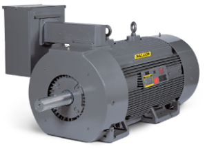
Screen Shot 2014-06-30 at 10.27.50 AMBaldor Electric Co. has introduced a new line of energy-efficient, large AC - GPM Induction Motors. Used in high-torque industrial applications, including pumps, fans, conveyors and compressors, the product line is available in stock ratings 250 – 1000 HP, 2300/4000 Volt, totally enclosed (TEFC), fan-cooled, foot mounted designs.

Features and benefits of the stock-motor lineup include:

  • Cast iron frame, end shields and inner caps
  • Insulated opposite drive end bearing
  • Drive end slinger
  • 100 ohm platinum winding RTDs
  • Provisions for bearing RTDs
  • Space heaters
  • Suitability for use on VFD 2:1 CT, 10:1 VT

The GPM line of large AC motors can also be ordered as custom items, ranging from 250 – 1500 HP, 460, 575, 2300/400 Volt, TEFC, in foot-mounted designs.

According to Baldor, stock, as well as custom units in this product family, can be used on variable frequency drives.

2087

3:19 am
June 26, 2014
Print Friendly

Expanded Lineup of Concentric Reducers for Heavy-Industry Applications


Screen Shot 2014-06-25 at 10.00.13 PMBaldor Electric Company has introduced an expanded line of heavy-duty concentric reducers in a full range of nine sizes, from 9800 in-lb. to 575,000 in-lb., and ratios from 2.25 to 194.6:1. According to the Baldor-Dodge Gearing Group, its Dodge Maxum XTR family of reducers is suited to use in grain, bulk-materials, steel, paper, wastewater and other heavy-industry applications where reliability and uptime are crucial.

Combining high-power capacities and harsh-duty capabilities as standard in ductile iron housings, the products incorporate a tandem sealing system that features an HNBR oil seal and contact excluder seal with a purge-capable grease capacity.

Offered with standard 3-year warranties, Maxum XTR reducers in select ratios with scoop motor mounts are in stock at Baldor’s Crossville, TN, warehouse.


Navigation